Category Archives: embedded

related to embedded systems engineering and/or firmware development

Dream Source Labs… so you thought Saleae sucked

When you untar the archive and everything’s marked executable, you know you’re in for a hard time. There is nothing easy or convenient about this thing.

Having said that it does work with Sigrok and Sigrok knows a lot of protocols. PulseView (the GUI front end to Sigrok) is okay but for heavy lifting you probably want sigrok-cli.

I just found it difficult to put the firmware (gateware for the FPGA) in the correct place–why don’t these things (Saleae’s the same way) just store the FPGA gateware in flash? Lastly, there are some things I like better about the Saleae’s software.

RISC V

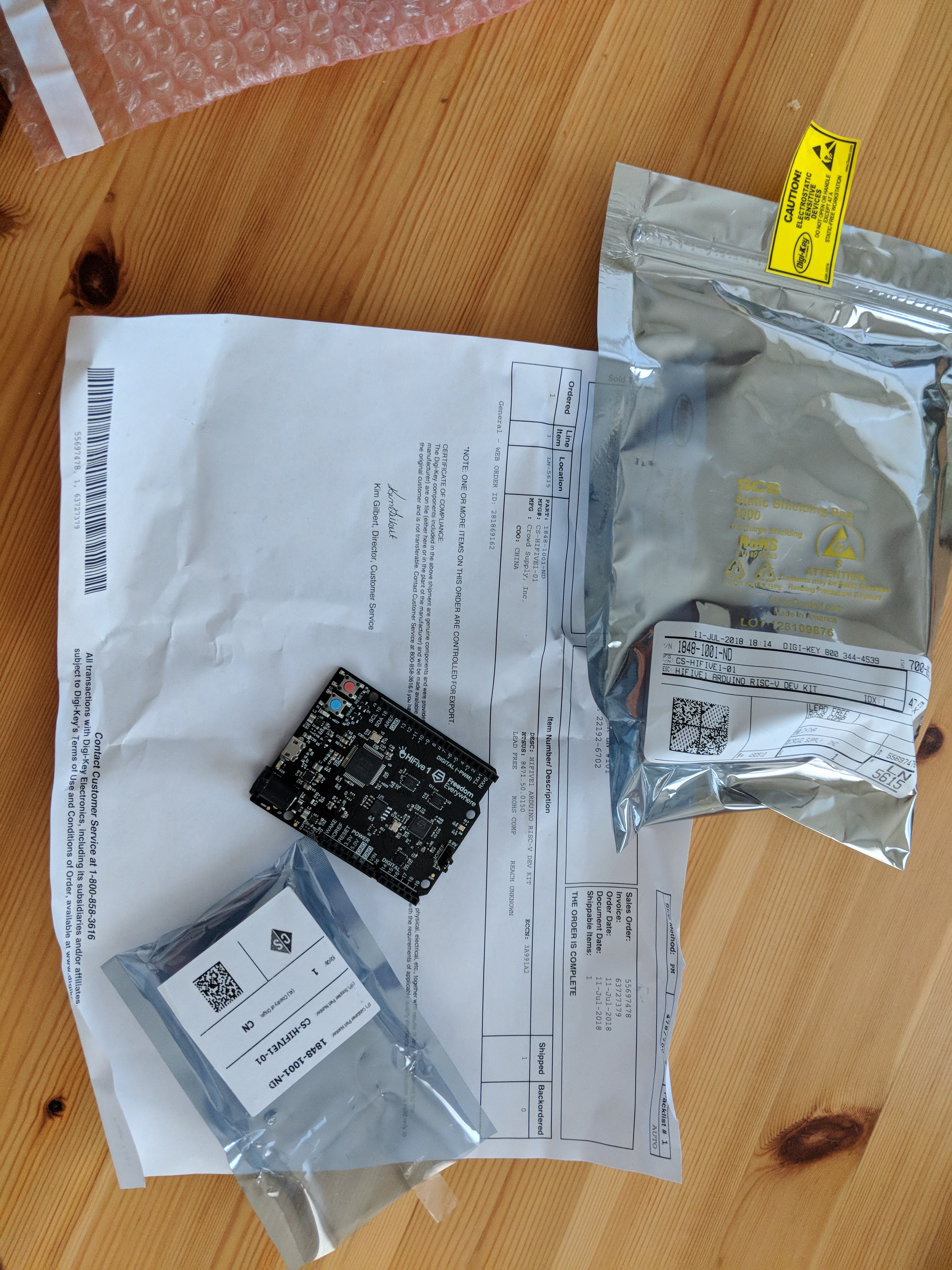
The HiFive 1 development board, got this a few months back, forgot to post.

So far I have OpenOCD sorta working–yea GDB!, well okay gdb’s not actually working for me yet. Yes I could just use the freedom SDK but that’s too easy! …and no I have no idea what I’m going to do with it, SDR radio transmitter, I dunno.

STM32F1xx, some advice

I have worked with the ST Micro ARM Cortex-M3 micro-controllers. I think I like them but here is some advice to help you along.

  • Yes, you really need all those capacitors. These things run at 75MHz or better. Put the caps close to the pins.
  • These things are more easily damaged by ESD than one might think. Yes, I know they’re supposedly marketed for automotive applications. Yes, I know the data-sheet says class blah blah blah. You need to do more, I had a product whose only vulnerability was the battery compartment and I still had to do more. I found this helpful
  • Build your own cross compiler from scratch! You will learn things about C/C++ that you need to know to be a good embedded systems engineer. I have some stuff like crt0 and linker scripts on this site. Yes I cut and pasted them but I was about 3/4ths of the way through writing them from scratch before I found prettier ones on-line and no, I did not waste my clients time, I was able to solve deep problems with other people’s projects at the same client because I understood this stuff. I stood on the shoulders of giants and here’s a link to one of those giants 🙂 The Olimex site also has some info for building a cross compiler.
  • I like and recommend the Olimex boards but they have the same ESD problems I had so don’t be lulled into a false sense of security, add mitigation to your design. I used a TVP diode between VDD and VSS on the line coming from the battery clip.
  • I have the FlySwatterII and the Olimex ARM-USB-OCD-H, I prefer the latter mostly because it can provide power.
  • Use the ST micro provided libraries sparingly, sometimes it’s easier to understand the peripheral and write your own code than to try to sort out their library madness or HAL.
  • OpenOCD and gdb are awesome. Yes gdb has a steep learning curve, no it’s not pretty, but it is the most powerful debugger known to man… The only thing I’ve ever seen that was close ran on a VAX when I was a kid. I find cgdb helpful. I sometimes use the layout stuff but it’s a bit young (read buggy) but helpful. Seriously, learn to cope with gdb it can do things no other debugger can.
  • Read the errata these things have a surprising number of hardware bugs!

PIC Microchip, some advice

I like 8bit PICs but here’s some advice:

  • You want to use assembly. Really, don’t mess with whatever crazy (non-ANSI) c compiler these clowns are pushing. Assembly (particularly on these chips) is not hard.
  • MPLAB X is horrible, it takes all the things I love about PICs and makes it complicated.*
  • Don’t mess with the PICkit3 it only works with MPLAB X. You want the PICkit2, it works with pk2cmd. If you really need those debugging features then it’s time to move on to something with an ARM core (Serial Wire Debug gdb and all that)
  • If you need to do math use a lookup table (array). If your math is complicated then do it in C and use something with an 32 bit ARM core (read: not a PIC); these things don’t have FPUs. Really, most of them multiply by adding in a loop, an FPU is like a pocket calculator for your CPU.
  • Use the simplest chip you need to do the job, start out with something with with a modest number of peripherals lest you be overwhelmed.
  • Really, learn assembler your going to get stuck anyway and have to write some assembly anyway… and it’ll make you feel smart!

* What they’re really up to here is to immerse you in their marketing madness. Hey Microchip, if ya want me to use your high end chips than you need to contribute to gcc or clang or both, if it’s not an open source ANSI compiler I won’t use it, I am not going to learn your crazy dialect of C or pay you for the privilege of writing code that will create demand for your chip!

Beacons using a PIC10F200

Before there were standards like iBeacon and Eddystone we had to “roll our own.” This is a primitive beacon using a PIC10F200 (8pin DIP) along with a simple 315MHz OOK transmitter. Later versions, not shown here, use SDR.

beacon.asm

This is written in PIC assembly. It simply transmits my FCC Call sign with a number tacked on the end. Production versions would substitute a UUID and checksum in place of my Call sign. The signal is intentionally weak, we only want to know if the watch (wearable device) is within a few meters. Battery life is important too, this thing should be good for about 57 years on a couple AAA batteries.

The gist of what this code does is to set a timer and go to sleep. When the timer expires the chip wakes up and increments some counter (the timer durations are rather short) and we need some randomization to minimize the possibility of interference betwixt proximal beacons*. If it’s time to send a burst, my Call sign, then it does so, resets the counter and timer and goes back to sleep. The idea is to spend as much time asleep as possible to conserve batteries.

beacon.asm

Makefile

* This is a bit tough to explain so bare with me. The oscillators on these things are not precise. So imagine we were to send a burst every 30 wake-ups (e.g. no randomization). Okay so lets say you have two of these close together and we put batteries in them at the same time. Now every 30 wake-ups they both wake up and clobber each other (the wearable can’t hear either because they “talk” over each other). Now eventually, because the oscillators are imprecise, they drift apart but that may take hours; therefore, we introduce some randomization to keep them asynchronous. I’m skipping some nuance here but I hope you get the idea.

Toaster Oven Re-Flow

This project involves a lot of teaching an old company some new tricks, but there are a million things that could go wrong with this stunt! My goal was to keep costs low as we flush out a new process for doing things. Toaster Oven re-flow is just what it sounds like. Instead to spending $10K on a re-flow oven I did some reading and convinced my boss, Larry Skutchan, that we should at least try this. My yield stands at about 80%. We have prototyped this whole product in-house, the only thing we sent out were the board spins.

The Prototype

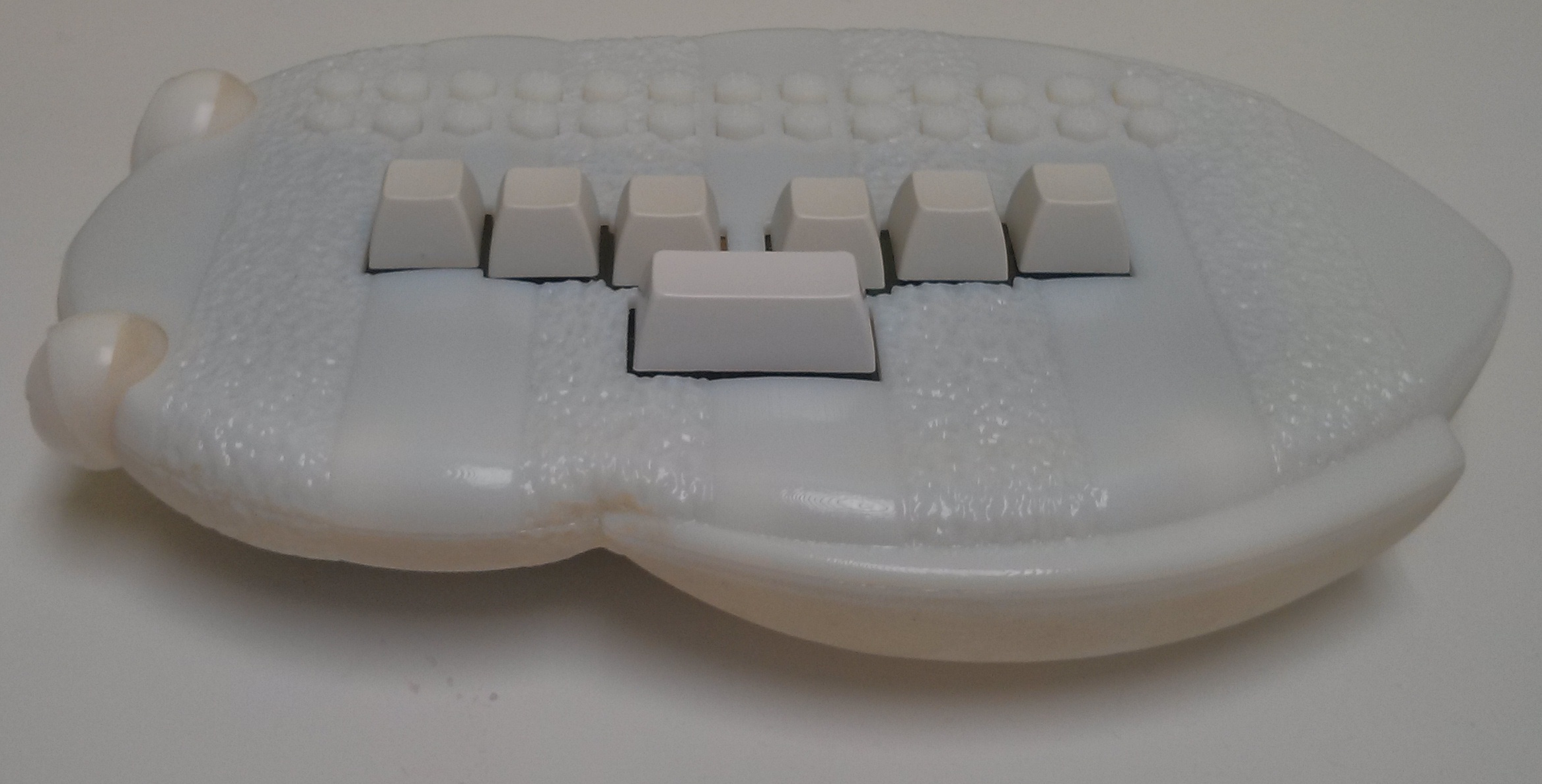
Here is the prototype fresh off the 3D printer! It was a real pleasure to work with Industrial Designer / Modeler Andrew Dakin  and Industrial Engineer / 3D printer guru Andrew Moulton, they took some very primitive ideas and turned them into something awesome! It’s hard to see but the 26 keys across the top have the Braille letters of the alphabet on them.BBPrototype

Braille Buzz Main Board

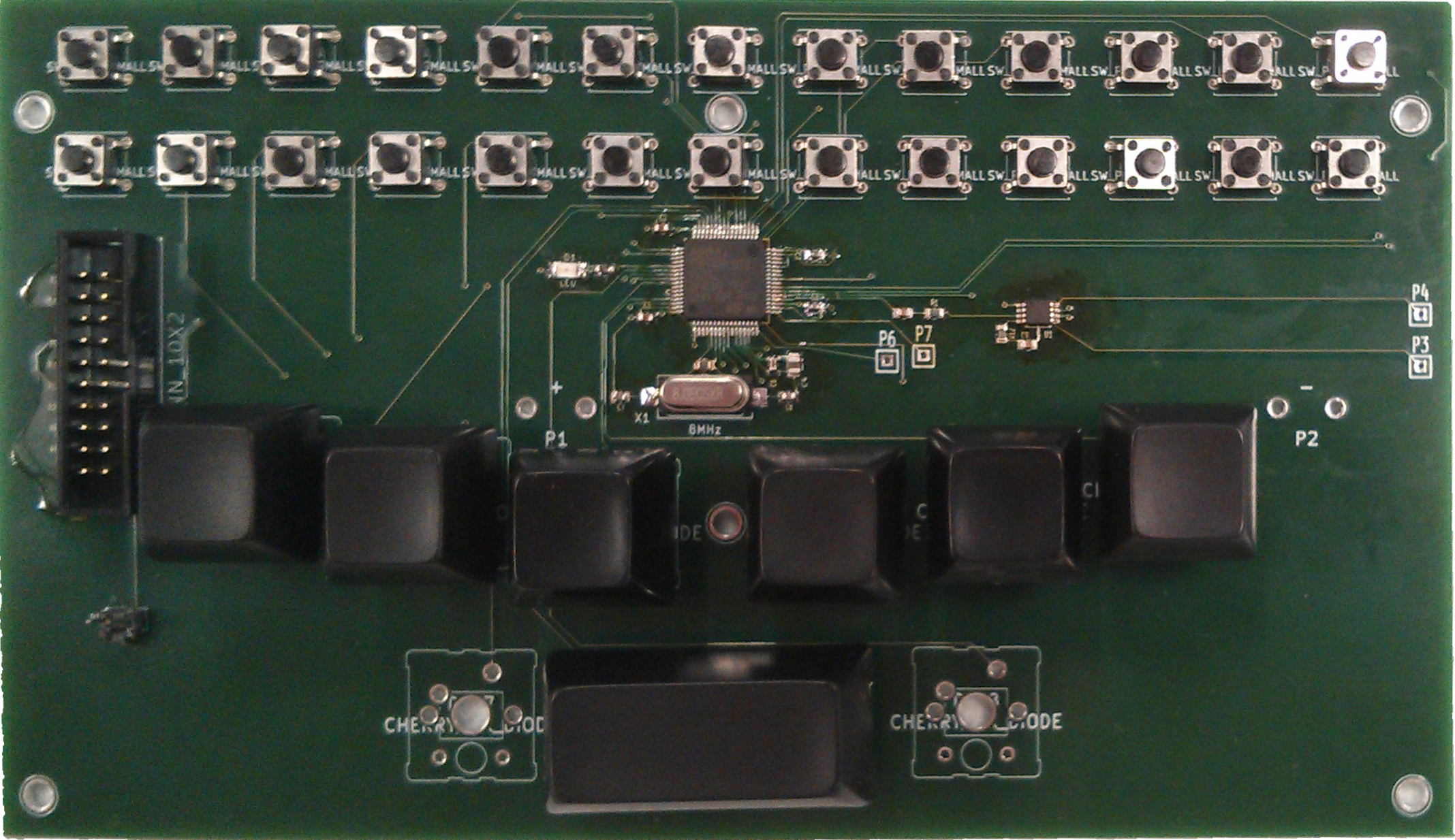
BBMainBoardV0.2This is the second board spin. I designed this board and product from scratch. I started with the data-sheets for the ST Micro chip, took some tips form the Olmex boards that featured a similar chip, crossed my fingers and it worked! I have used Eagle (very popular), and Altium (very complicated), and I even tried PCB (too primitive) but my favorite is kiCad (just right). I suspect Verilog can be used for PCB layout, it’s really for “programming” logic gates, but I have my suspicions that it could be a good choice for really complex PCBs.

OpenOCD for BrailleBuzz (STM32F103)

This is my convenience stuff for working with openOCD. “debug” loads the “executable” bin and halts the MCU. “run” loads the “executable” bin and starts it running. “samples” loads some data in to the second bank of flash.

Compile environment for BrailleBuzz (STM32F103)

Okay three big topics here: crt0 (also known as c0), crt1 (also known as c1), and the linking scripts. crt0 is the code that needs to run before your main, it sets up things like the stack. crt1 is the low level stuff that would normally be OS calls. I sorta simulate an OS because we don’t have one, so I simulate a heap and malloc, etc. The linking scripts tell the linker where to put things in the address space.

crt0

This is the code that executes before your main function gets called. Execution starts at 0000h (actually it may be a pointer on this implementation). But before one can actually run any C one has to do some set-up stuff. Traditionally one writes crt0 in assembly and indeed my original was in assembly. If your careful and don’t use certain C constructs you can write crt0 in c itself. There is heavy interaction with the linker script as we need to prepare things like the BSS, EBSS, stack etc. Remember C is gonna need to know where in the address space (which changes from implementation to implementation) things like RAM(rw), flash(ro) and heap are.

crt0.c

crt1

This is the low level operating system type stuff. Well, we don’t have one, but we’d still like things like printf and malloc to work or at least not crash. Remember after you call printf, somewhere down the pike some ascii (or unicode) has to go somewhere. In our case we’re going to output it to one of the UARTs. This is very convenient when debugging! This code took a long time to sort out and is incomplete. I got some of the stubs from the manufacturer. Recall that in a unix OS we would be opening files (in dev), reading from and writing to them but here we don’t have an OS or a file-system so we make some assumptions, lots of assumptions.

crt1.h

crt1.c

linker script

We need to tell the linker where to put things. What addresses correspond to RAM? What addresses correspond to ROM(flash)? Where’s the “heap”, how big is it.

stm32.ld

IRQ handlers

Lastly we have the irq handlers. We mostly just go into an infinite loop. Naturally we really should do better than this but I never got round to it.

irq.h

irq.c